Homepage

Mostrando las entradas con la etiqueta wifi. Mostrar todas las entradas

martes, 20 de septiembre de 2016

Update ESP8266 Industrial Modbus TCP IP V2.0


There have been numerous applications in the ESP8266, I have taken as a goal to integrate this module into one of the industrial protocols most commonly used Modbus TCP IP, it would be good to have a node or sensor that sends data or a driver, OPC, PAC, PLC, HMI or SCADA.

A long time ago I found a group of people in forums.adafruit already had an advance and example have been implemented and improvements suggested by ibbba for the contribution.
The programming code for ESP8266 in this case was implemented in Arduino IDE versions 1.6.4 above. These 2 tutorials indicate connection and basic programming ESP8266 01 and 03 modules.

TUTORIAL

TUTORIAL
Previous tests library ModbusTCPSlave
ESP8266 - 01 Modbus Slave TCP IP (Ethernet) for Industrial Applications

CONCLUSIONS
In previous tests with the library Original ModbusTCPSlave, it had two drawbacks of application:
Code Execution
properly functioning communication modbus tcp, but do not run the code in the routine void loop, as a temporary solution the library for ESP8266 amending stop the connection and reconnect again, the problem with this method is time reconnection can make the teacher while accepting the data indicate error in data reception.
Serial port
Originally ESP8266 the serial port was used as a debug port in hexadecimal, I have made changes to the library so that Serial can be used freely.

                           VIDEO Update ESP8266  Industrial Modbus TCP IP   V2.0
IMPROVEMENTS
With the new modifications it has been omitted disconnection allowing a constant flow of communication if stop the connection between the ESP8266 and modbus tcp master mandatory.
Ticker
He has implemented Ticker library created and documented by igrr, it is an object to call a given function with a certain period. Each Ticker calls a function. You can have as many as you like tickers, the only memory limitation.

Important note: When creating tickers consider not create any delay would affect both modbus communication protocol, such as the execution of that function.


TESTING
the connection between the ESP8266 and a simulator configured as master Modbus tcp was made.
-initially The Ticker Parada is created.

CODE DESCRIPTION
call the function value is created and defined 2 Holding Registers:
Mb.MBHoldingRegister[0] =  Holding Registers 1
Mb.MBHoldingRegister[1] =  Holding Registers 2

Mb.MBHoldingRegister[0]  send a random(0,51) value to the Modbus Master and validate the upgrade value.

Mb.MBHoldingRegister[1]  is used for reading a value sent from the Modbus Master and from the serial terminal validate the update.

modbus routine Mb.Run();  is executed; and execute the Ticker Parada.attach_ms(25,valor); every 25ms doing the value created in the function.

Taking this example as a basis, they could perform management functions for I / O similar and digital, load and others, taking only into account not implement any delay.
POSSIBLE INDUSTRIAL APPLICATIONS


                                                                 TUTORIAL
Industrial software integration with OPTO 22

Downloads Github
Code  ESP8266_Industrial_ModbusTCP_V2

References
Arduino Mega 2560 Oled Display I2C Master Modbus RTU Scada Industrial Connection
Arduino + ESP8266 + Software Opto22 example Scada Industrial

More Info:

Youtube Channel
PDAControl


jueves, 7 de julio de 2016

Turn led ESP8266 with Thinger.io


This time a test is carried out with the Thinger.io platform, using a 01 ESP8266 be conducted remotely control a diode led directly from the web platform.
As shown by a LED diode will control but the application can be with relay actuators and others.

Requirements:

Turn led ESP8266 with Thinger.io

Api control device

 Arduino IDE Code


Test


Materials

1  - 1 ESP8266 - 01
2  - 2 Converter FTDI  Serial -Usb ttl
3  - 3 Regulator 5 a 3.3v
4  - 1 diode led
5  - 1 resistor de 220 Ohm

Connections


Downloads 


More Info:

Youtube Channel
PDAControl

miércoles, 6 de julio de 2016

Introduction Plataform IoT Thinger.io


This time I bring this IoT platform called Thinger.io, in this tutorial as NOTED create an account to register our devices either Arduino, Raspberry Pi or other data collection platform in my case tests effected, with the ESP8266 01.

This platform allows monitoring and control of variables without any complications.
page Oficcial : https://thinger.io/


You want to try thinger.io? The following video will show you step by step


Preview


Report data transmission


Number of Devices
Register for free allows 3 devices with a limit of sending requests monthly 100mb


Geolocation
It has geolocation of connected devices.


Testing - Video tutorial


More Info:

Youtube Channel
PDAControl
Test ESP8266 + DS18B20 Onewire + Google Speadsheets (Google Docs)


If we want a simple solution to monitor temperature, for complicate applications?
if we have Google Docs, This test perform temperature measurement using a probe DS18B20 and transmit directly to  Google spreadsheets using as Google app script bridge.
For this test approximately every 10 seconds temperature data was sent.

Requirements
Arduino IDE
Programming ESP8266
Google Docs account


Connection ESP8266 and Google spreadsheet (Google Docs) Direct
I tested the bookstore Library HTTPSRedirect created by Sujay hadke (electronicsguy) thanks for their contribution to the ESP community, in your example creates a kind of chat between Google Docs and ESP8266, below a tutorial video where settings are explained and Connection.


Important note:
To perform this test is required to see the previous tutorial, settings for Google script and Google spreadsheets, Below are the sofware related to this project.

probe DS18B20


Google Spreadsheets Sheet

This sheet has the following characteristics:

1. Historical Record
2. Graph Historical
3. Dial for Current Status


Video Tutorial
Materials

1  - 1 ESP8266 - 01
2  - 2 Converter FTDI  Serial -Usb ttl
3  - 3 Regulator 5 a 3.3v
4  - 1 Sensor DS18B20


Downloads  Github  Project

Related

More Info:

Youtube Channel
PDAControl


lunes, 27 de junio de 2016

Control outputs ESP8266 with Google spreadsheets (Google docs)


How many times have looked like lighting a led from the Internet, not a local network from the Internet, there is a very useful way to light a GPIO ESP8266 from Google Spreadsheets,, but first must see this complete tutorial ESP8266 direct connection to Google Spreadsheets (Google Docs).


Programming ESP8266 with Arduino IDE in 5 minutes
To make this example must know and program the Arduino IDE ESP8266-01 below a tutorial


Connection ESP8266 and Google spreadsheet (Google Docs) Direct
I tested the bookstore Library HTTPSRedirect created by Sujay hadke (electronicsguy) thanks for their contribution to the ESP community, in your example creates a kind of chat between Google Docs and ESP8266, below a tutorial video where settings are explained and Connection.


Control outputs  ESP8266  with Google spreadsheets (Google docs) Direct

I have made changes to the library so you can control the GPIO 2 of our ESP8266, writing on or off, the ESP is constantly done reading cell A2.
Modifications
Temporary change in library HTTPS Redirect.ccp to turn GPIO2, receiving the socket "On \ r"or "Off \ r".
IMPORTANT NOTE: For this example must download the modified libraries, link down on downloads.


Test Circuit

Materials

1  - 1 ESP8266 - 01
2  - 2 Converter FTDI  Serial -Usb ttl
3  - 3 Regulator 5 a 3.3v
4  - 1 diode led


Downloads  Github  Project

Related

More Info:

Youtube Channel
PDAControl


lunes, 20 de junio de 2016

ESP8266 direct connection to Google Spreadsheets (Google Docs)


In the following step by step video tutorial will explain the connection of ESP8266 with script and google Google Spreadsheets.
HTTPSRedirect Library 
We used the Library HTTPSRedirect created by Sujay Phadke (electronicsguy) thanks for their contribution to the community ESP,
For connection the following is required:
GoogleDocs.ino (File Arduino IDE)
HTTPSRedirect (Library)
Code.gs (Google Script Archive)


Industrial Application Modbus RTU RS232 


Downloads

Related Projects

More Info:

Youtube Channel
PDAControl

sábado, 18 de junio de 2016

ESP8266 program with Arduino IDE in 5 minutes


This ESP8266 default module that works by AT commands, thanks to the contributions of the community has made integration with Arduino IDE.

This module (ESP8266) integrates the capabilities of an Arduino + Wifi (Ethenet) and easily the perfect combination for more or less one dollar, just personally I use in my applications in industrial integration, this module is perfect.

Installing ESP8266 in Arduino IDE is only valid from version 1.6.4 and above, in my case there are newer versions but I liked the version 1.6.4 and it worked perfect.

Video step by step explanation Installation and configuration Arduino IDE


Materials 
1 ESP8266 - 01
1 Conventer FTDI Usb - ttl serial 
3 Regulator de 5v a 3.3v
2 Pushers
1 resistor10k
1 Diode Led

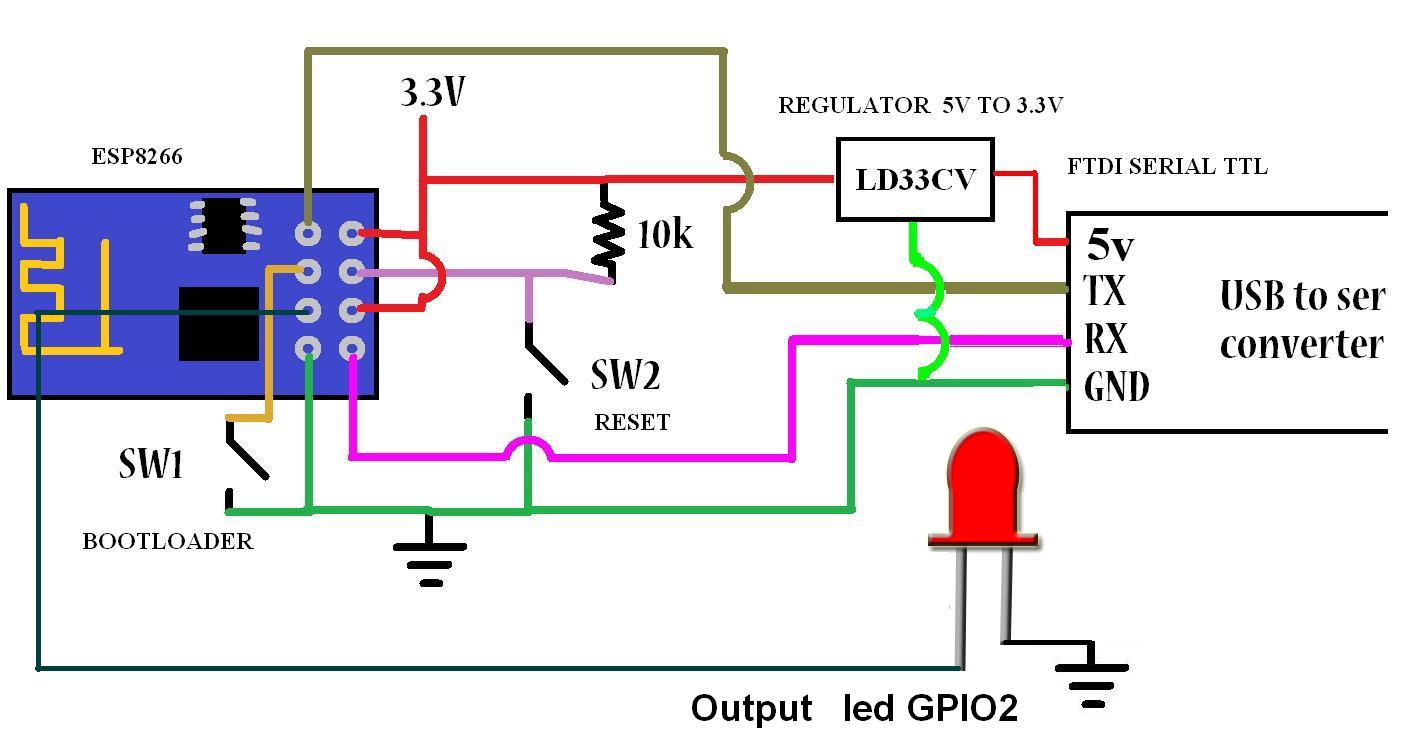
Connections
SW1 = GPIO 0 (this pin to LOW = Bootloader Mode - Programming Mode)
SW2 = RST Reset (reset pulse module)

ESP8266 PINOUT

INSTALLATION, CONFIGURATION AND PROGRAMMING
With the next step you programmed your ESP8266 with Arduino IDE:

Step 1 . Download copy Boards Github: https://github.com/esp8266/Arduino


Step 2 . Open Preferences Arduino IDE and paste additional board
http://arduino.esp8266.com/stable/package_esp8266com_index.json


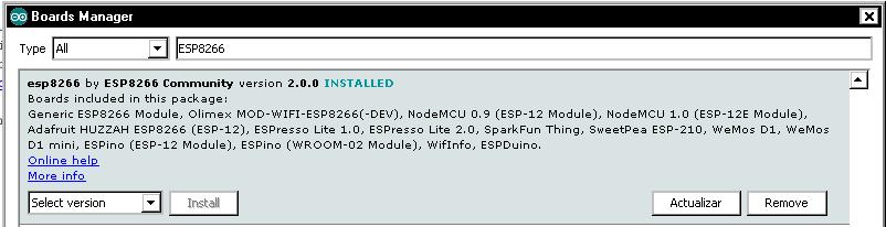
Step 3. Open Board Manager


Step 4. Search ESP8266 install library


Step 5. Open Board to select and configure ESP8266 Generic.


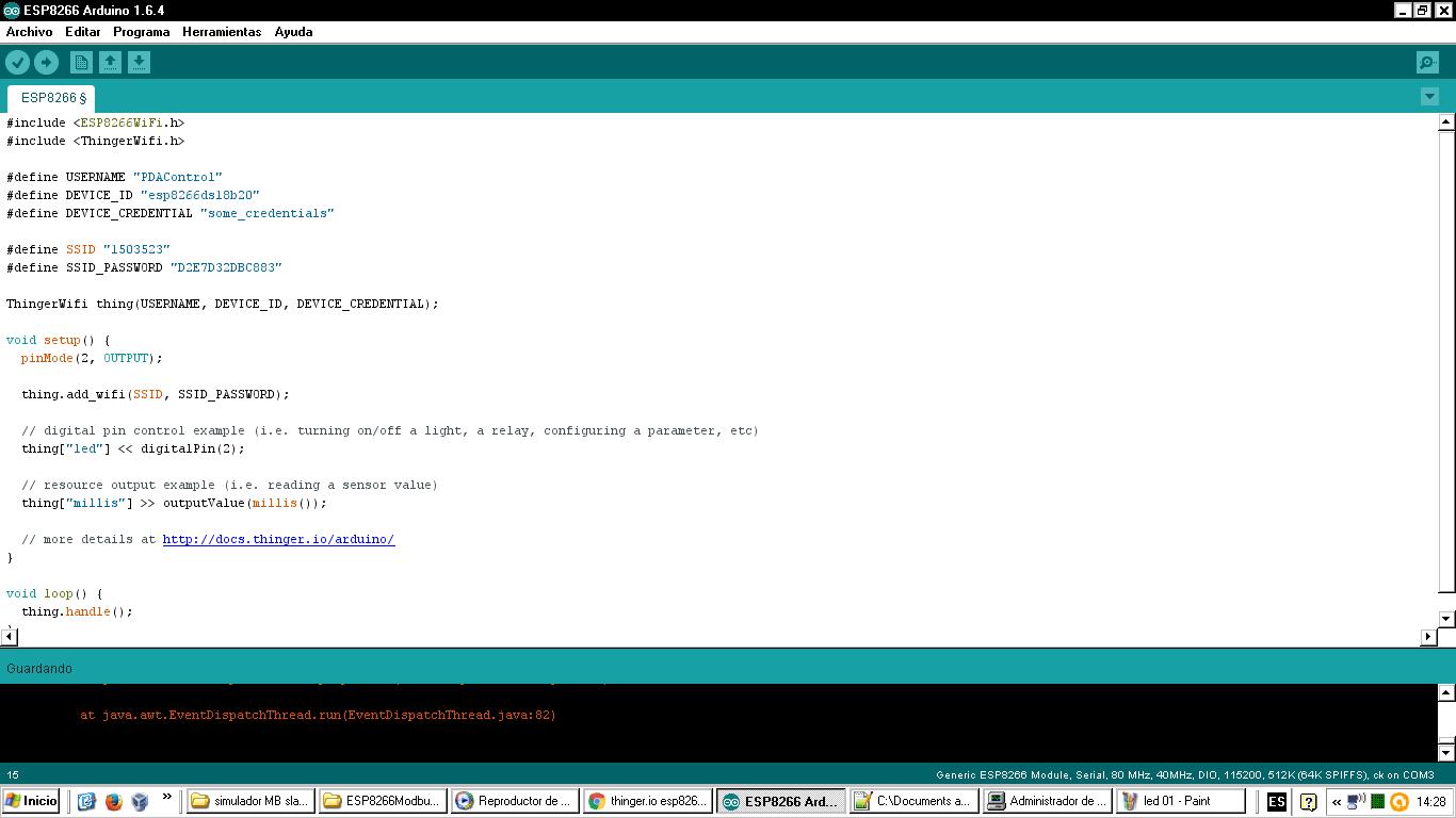
Step 6. Prepare Blink code example using the GPIO 2 output.


Step 7. Place GPIO0 (SW1) to position LOW Bootloader mode


Step 8. A pulse SW2 (Reset) and SW1 = LOW


Step 9. Keep GPIO SW1 = LOW

Step 10. Download code (Blink)


- Uploading Code


- The ESP8266 and FTDI module should flash


- Code uploaded to ESP8266


Step 11. Switch SW1 and SW2 Reset with a pulse (RST)


Step 12. RUN mode, the program should run normally

Step 13. Connect diode led to GPIO 2


Ready....

If set again ESP8266 mode AT commands with the same circuit and can configure the following video by Default, upload firmware by default.

ESP8266 firmware update with Flasher ESP8266


More info:


Youtube Channel


viernes, 27 de mayo de 2016

Arduino + ESP8266 + Software Opto22 example Scada Industrial


Has made the integration of Arduino + ESP8266  + Software Opto22, implementing its environment scada right through IP and Modbus TCP Modbus RTU, the idea is to implement this hardware in the industry for both monitoring and control.

1- Arduino MEGA 2560 Master Modbus Potenciometer Display  Oled 
The Arduino configured as Modbus RTU master sends the value of the potentiometer to the slave in this case a slave simulator.
More info :  


2- ESP8266 Bridge  Slave Modbus TCP - Slave Modbus RTU 
ESP8266 test Registers as a bridge between Modbus RTU and Modbus TCP IP (Ethernet)
More info:


3- Arduino Mega 2560 + ESP8266  Modbus RTU Modbus TCP IP Industrial Applications
ESP8266 + Arduino Mega ready to connect to SCADA OPC PLC  Performing a mixed industrial network Modbus RTU Modbus TCP IP
More info: 


4- Installation PAC Project Basic and  Simulator PAC Sim
process software download and installation of software for Opto 22 controllers in this case download the PAC Project Basic, which includes software programming, design HMI and SCADA Runtime
More info: 


5- Download Strategy Modbus TCP IP Master in PAC Project Basic Opto22 
Opto22 example of strategy setting according to requirement as master or slave Modbus TCP, in this case for integration is configured as Modbus TCP master is discharged are configured holding registers for reading and writing respecting addressing.
More info:


Final test
Arduino ESP8266 SCADA Industrial integration on Opto 22 
This is the integration of the previous 5 tutorials
Arduino + ESP8266 + PAC Project Basic + PAC  SIM


Photos tests
Display Oled

ESP8266
Arduino Mega 2560


Materiales
1 Arduino MEGA 2560
1 ESP8266-01
1 Display Oled 128x64 I2C
1 Potenciometer 100k
1 protoboard
1 Battery 6v lead acid
1 Regulator 5 - 3.3 vdc
wires

                                                     Conections  Arduino Mega 2560
  Conections ESP8266 
Pac Display Runtime Online
SCADA HMI 

Pac Project Basic 
Programing


Downloads
Arduino IDE Code


More Info:

Channel Youtube