Tutorial ESP8266 Control Servo Node-RED MQTT (Mosquitto) IoT #2

This time the integration of ESP8266 and the Node-RED platform has been made integrating an actuator in this case a servo controlled by PWM with rotation from 0 to 180 degrees.
From an HMI or SCADA Web creator on Node-Red-Dashboard using as base the MQTT Protocol and pubsubclient library converting the ESP8266 into MQTT Client.
Previous tutorials Recommended
icstation.com
Tutorial 1 : Install Lubuntu (Ubuntu)
Tutorial 2 : Installation node red platform
Tutorial 3: Installation Node Red Dashboard
Tutorial 4: Installation Modbus TCP IP in Node Red
Tutorial 5: Installation of Mosquitto Broker MQTT in Lubuntu
Tutorial 6: Program ESP8266 con Arduino IDE
Tutorial 7: ESP8266 and Node-RED MQTT GPIO # 1
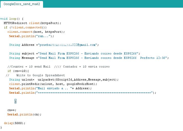
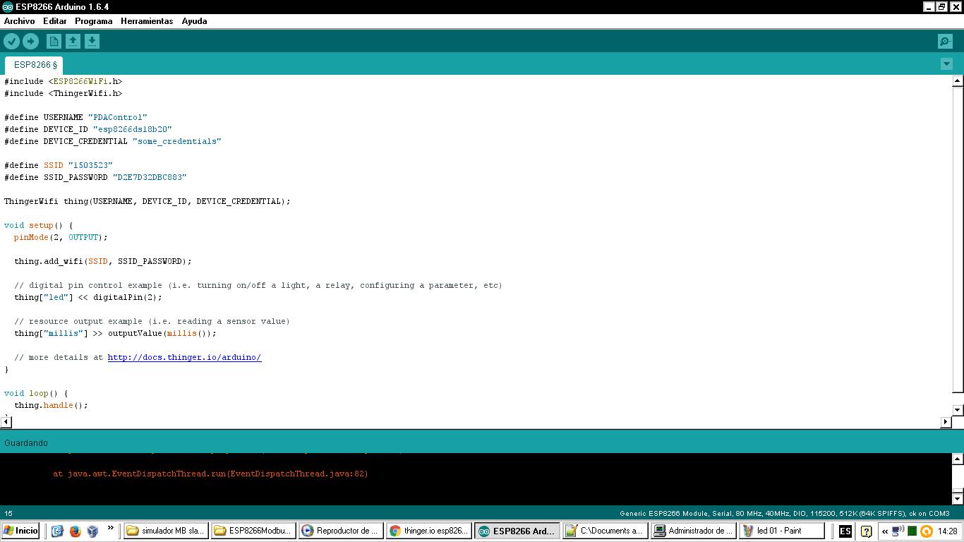
Arduino IDE
The ESP8266 module has been configured as an MQTT client, as subscriber of the "servo" topic, the ESP8266 will receive a value from 0 to 100% and will convert it from 0 to 180 degrees for servo control via PWM by GPIO 02.

Mosquitto MQTT Broker
Previously it has been installed in a computer with lubuntu (Ubuntu) Linux, the server Broker MQTT which performs the management of messages in the network, Mosquitto has been used in this case.
Node-Red
A sequence of nodes has been created to send data from the Dashboard.

Node-RED-Dashboard
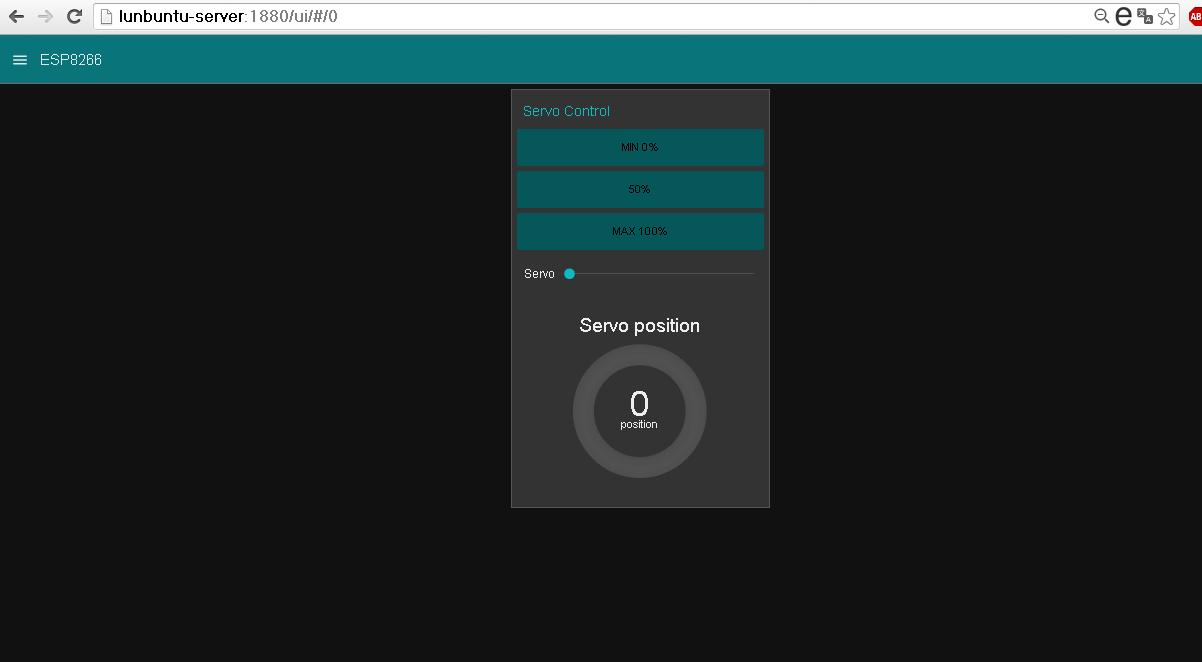
View Tablet


Video Tutorial ESP8266 Control Servo MQTT Node-Red IoT #4
Materials
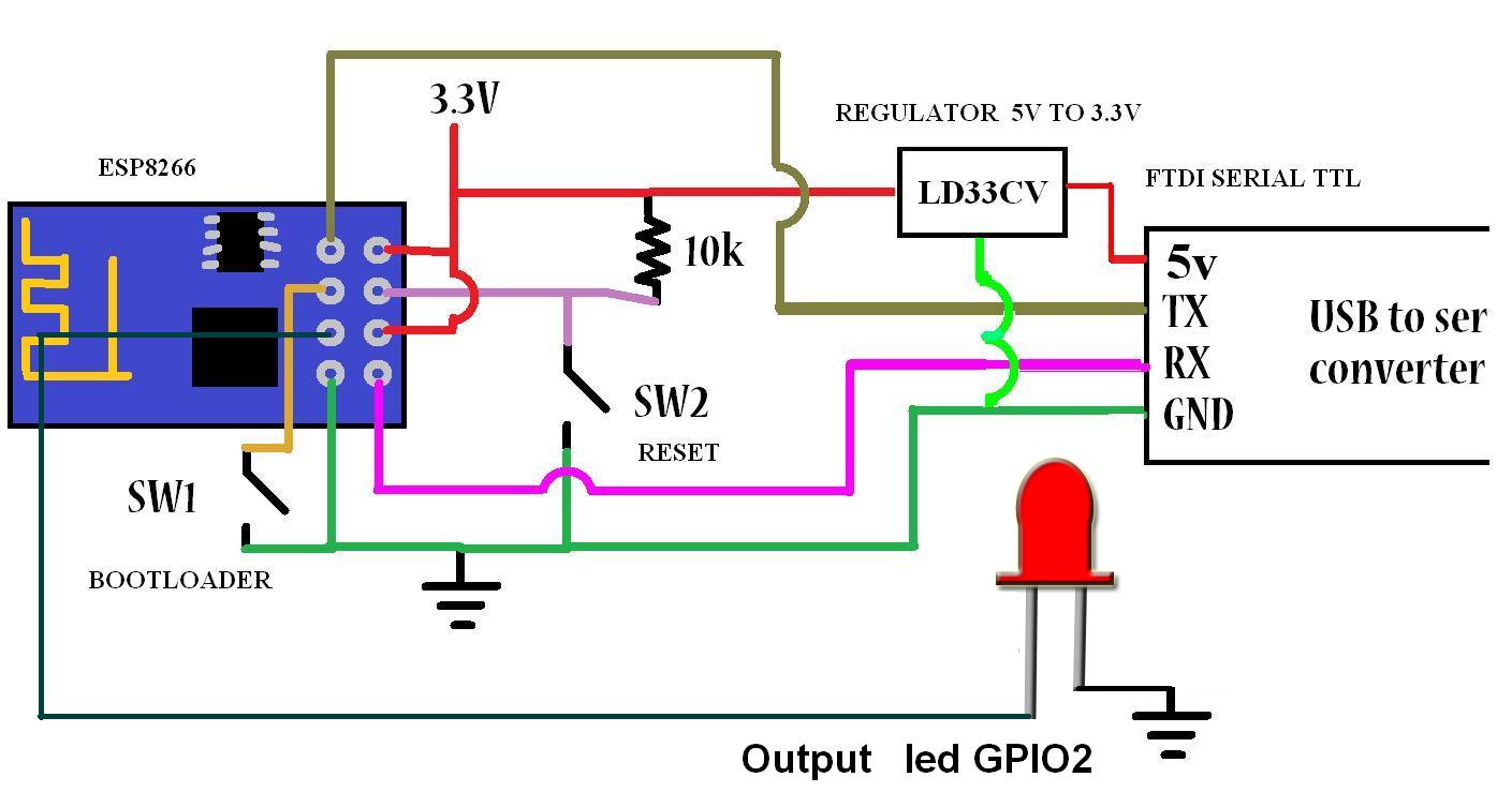
1 ESP8266 01
1 Regulator LDV33CV 5 a 3.3V
1 Chip FTDI Serial
1 Servo Mystery control PWM
Connections

Where to buy?
icstation.com
ESP8266 01 (ESP 01)
Github Arduino IDE code ESP8266 MQTT
Github pubsubclient Library
Node Red import code example
References
icstation.com
Tutorial 1 : Install Lubuntu (Ubuntu)
Tutorial 2 : Installation node red platform
Tutorial 3: Installation Node Red Dashboard
Tutorial 4: Installation Modbus TCP IP in Node Red
Tutorial 5: Installation of Mosquitto Broker MQTT in Lubuntu
Tutorial 6: Program ESP8266 con Arduino IDE
Tutorial 7: ESP8266 and Node-RED MQTT GPIO # 1
Nodered.org
github.com/node-red
Nodejs.org
More Information:
Youtube Channel: