In the search for attachable communication protocols Node-Red I found thanks to the collaborative development a library or nodes for communication Modbus TCP IP, the following tutorial is indicated as installing the nodes inlubuntu (Ubuntu).
This library node-red-contrib-modbustcp was created by Jason D. Harper was based on the jsmodbus library, this library allows our Node-Red server is configured as master Modbus TCP, it contains 2 nodes one reading and one writing .
There have been numerous applications in the ESP8266, I have taken as a goal to integrate this module into one of the industrial protocols most commonly used Modbus TCP IP, it would be good to have a node or sensor that sends data or a driver, OPC, PAC, PLC, HMI or SCADA.
A long time ago I found a group of people in forums.adafruit already had an advance and example have been implemented and improvements suggested by ibbba for the contribution.
The programming code for ESP8266 in this case was implemented in Arduino IDE versions 1.6.4 above. These 2 tutorials indicate connection and basic programming ESP8266 01 and 03 modules.
Previous tests library ModbusTCPSlave ESP8266 - 01 Modbus Slave TCP IP (Ethernet) for Industrial Applications CONCLUSIONS
In previous tests with the library Original ModbusTCPSlave, it had two drawbacks of application: Code Execution
properly functioning communication modbus tcp, but do not run the code in the routine void loop, as a temporary solution the library for ESP8266 amending stop the connection and reconnect again, the problem with this method is time reconnection can make the teacher while accepting the data indicate error in data reception. Serial port
Originally ESP8266 the serial port was used as a debug port in hexadecimal, I have made changes to the library so that Serial can be used freely.
VIDEO Update ESP8266 Industrial Modbus TCP IP V2.0
IMPROVEMENTS
With the new modifications it has been omitted disconnection allowing a constant flow of communication if stop the connection between the ESP8266 and modbus tcp master mandatory.
Ticker
He has implemented Ticker librarycreated and documented by igrr, it is an object to call a given function with a certain period. Each Ticker calls a function. You can have as many as you like tickers, the only memory limitation.
Important note: When creating tickers consider not create any delay would affect both modbus communication protocol, such as the execution of that function.
TESTING
the connection between the ESP8266 and a simulator configured as master Modbus tcp was made.
-initially The Ticker Parada is created.
CODE DESCRIPTION
call the function value is created and defined 2 Holding Registers:
Mb.MBHoldingRegister[0] send a random(0,51) value to the Modbus Master and validate the upgrade value.
Mb.MBHoldingRegister[1] is used for reading a value sent from the Modbus Master and from the serial terminal validate the update.
modbus routine Mb.Run(); is executed; and execute the Ticker Parada.attach_ms(25,valor); every 25ms doing the value created in the function.
Taking this example as a basis, they could perform management functions for I / O similar and digital, load and others, taking only into account not implement any delay.
The OPC (OLE for Process Control) is a communication standard in the field of control and monitoring of industrial processes, based on Microsoft technology, which provides a common interface for communication that allows individual software components to interact and share data. The OPC communication is done through a client-server architecture. The OPC server is the data source (such as a hardware device at plant level) and any OPC-based application can access that server to read / write any variable offered by the server. It is an open and flexible to the classic problem of proprietary drivers solution. Virtually all major manufacturers of control systems, instrumentation and process have included OPC in their products.
In short this industry standard allows intercommunication between devices and controllers Indistriales protocols almost all brands, performed monitoring and control from HMI, SCADA, PLC and RTU PAC'S
The OPC servers contain the drivers and / or communication protocols of the vast majority of industrial controllers
The OPC clients can be created in a variety of programming languages for reading and / or writing data to the server and there to the industrial controllers. Examples of Architecture OPC (PLC Sensors Actuators - OPC Server and Client OPC)
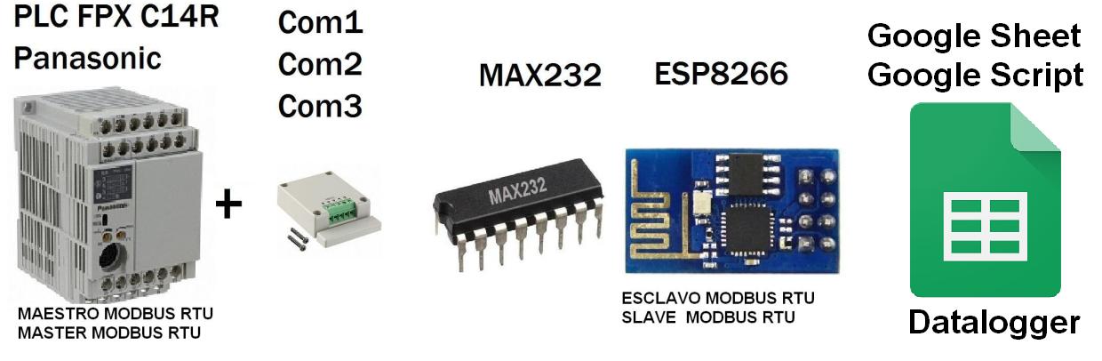
You want to monitor values of a PLC, controller, OPC, HMI or SCADA that is Master Modbus RTU and write in spreadsheets from Google (Google Docs), In this case we will monitor the value of potentiometer V0 PLC from 0 to 100%:
Potentiometer V0 (0-1000 SCALE 0 -100%)
Architecture
ESP8266 Connection Script and Google - Google Spreadsheets
-01 ESP8266 connecting with Google Script and connection with the spreadsheet from Google (Google Docs) Direct.
Based on the library HTTPS Redirect for ESP8266 of electronicsguy Github I have set and have made several improvements, I created the following tutorial full to Connect ESP8266 with (Google Script) and (Google Spreadsheets)
Has made the integration of Arduino + ESP8266 + Software Opto22, implementing its environment scada right through IP and Modbus TCP Modbus RTU, the idea is to implement this hardware in the industry for both monitoring and control.
1- Arduino MEGA 2560 Master Modbus Potenciometer Display Oled
The Arduino configured as Modbus RTU master sends the value of the potentiometer to the slave in this case a slave simulator.
4- Installation PAC Project Basic and Simulator PAC Sim
process software download and installation of software for Opto 22 controllers in this case download the PAC Project Basic, which includes software programming, design HMI and SCADA Runtime
5- Download Strategy Modbus TCP IP Master in PAC Project Basic Opto22
Opto22 example of strategy setting according to requirement as master or slave Modbus TCP, in this case for integration is configured as Modbus TCP master is discharged are configured holding registers for reading and writing respecting addressing.
Given previous post, this time it has been implemented ESP8266 Bridge Industrial Modbus protocol, in next tutorials will make the connection ARDUINO ESP8266 and SCADA HMI.
Explaining project ESP8266 module,
1 - It is configured by your serial port Modbus RTU Slave Serial, complementing a MAX 232 chip can convert from TTL to RS232.
2 - It is set by the wireless part - WLAN is configured as Modbus Slave TCP IP through the port 502,
3 - internally in the module 20 records both Modbus TCP IP Modbus RTU as follows redirected:
Modbus RTU -> Modbus TCP IP
From the Registry 0-9 Modbus RTU slave to the registers 0-9 Modbus TCP slave, all that is written in the first 10 records Slave RTU will be sent in the first 10 TCP Slave:
Modbus TCP IP --> Modbus RTU
From the Registry 10-19 Modbus TCP slave IP to records 10-19 Modbus RTU slave, all that is written from register 10 Modbus TCP slave IP registers be sent from the RTU Slave 10.
Opto 22 is a manufacturing company specializing in hardware and software for industrial automation, remote monitoring, and data acquisition. The company is headquartered in Southern California and is well known in the industry automation and control of its history of innovation in the development of Ethernet relay output status and input / based systems and Controllers.
From Wikipedia Opto22. Official page Opto22.com .
Introduction
This tutorial will tell you how to download and install the software PAC Project basic for creating HMI scada design and configuration generally based strategies controllers Opto22, then we will make integrations with Arduino and ESP8266 Software Opto22 .. Get ready !!.
PAC Project Basic
This software package is mainly divided into 3:
PAC Control Basic
Entrono building control strategy using 2 programming languages, traditional flowchart and similar or derived language c optoscript, also allows the creation and configuration of PID control loops, the main routines are chart or charts and allows creation Subroutines.
PAC Display Configurator
Creation Environment SCADA or HMI interaction is configured with drivers using a simbol Factory or libraries industrial simbologia (pushbuttons, actuators, pipes, pumps etc), it allows the creation of graphics and trend setting animations shift change colors etc. .
PAC Display Runtime
This application publishes and runs in real time on our HMI or Scada.
Others...
PAC Manager
Software maintenance visualuzacion of variables and more specific settings for Opto 22 controllers.
PAC Sim - simulator Opto22
Opto 22 has a equvalente simulator to have a driver Opto22 one that runs on your PC and have a time of testing and operation since it is a simulator, but in their version PAC Project Professional has SoftPac which if a controller in Software.
Video of downloading and installing PAC Project + Simulator PAC Sim on Windows