The OPC (OLE for Process Control) is a communication standard in the field of control and monitoring of industrial processes, based on Microsoft technology, which provides a common interface for communication that allows individual software components to interact and share data. The OPC communication is done through a client-server architecture. The OPC server is the data source (such as a hardware device at plant level) and any OPC-based application can access that server to read / write any variable offered by the server. It is an open and flexible to the classic problem of proprietary drivers solution. Virtually all major manufacturers of control systems, instrumentation and process have included OPC in their products.
In short this industry standard allows intercommunication between devices and controllers Indistriales protocols almost all brands, performed monitoring and control from HMI, SCADA, PLC and RTU PAC'S
The OPC servers contain the drivers and / or communication protocols of the vast majority of industrial controllers
The OPC clients can be created in a variety of programming languages for reading and / or writing data to the server and there to the industrial controllers. Examples of Architecture OPC (PLC Sensors Actuators - OPC Server and Client OPC)
You want to monitor values of a PLC, controller, OPC, HMI or SCADA that is Master Modbus RTU and write in spreadsheets from Google (Google Docs), In this case we will monitor the value of potentiometer V0 PLC from 0 to 100%:
Potentiometer V0 (0-1000 SCALE 0 -100%)
Architecture
ESP8266 Connection Script and Google - Google Spreadsheets
-01 ESP8266 connecting with Google Script and connection with the spreadsheet from Google (Google Docs) Direct.
Based on the library HTTPS Redirect for ESP8266 of electronicsguy Github I have set and have made several improvements, I created the following tutorial full to Connect ESP8266 with (Google Script) and (Google Spreadsheets)
Opto 22 is a manufacturing company specializing in hardware and software for industrial automation, remote monitoring, and data acquisition. The company is headquartered in Southern California and is well known in the industry automation and control of its history of innovation in the development of Ethernet relay output status and input / based systems and Controllers.
From Wikipedia Opto22. Official page Opto22.com .
Introduction
This tutorial will tell you how to download and install the software PAC Project basic for creating HMI scada design and configuration generally based strategies controllers Opto22, then we will make integrations with Arduino and ESP8266 Software Opto22 .. Get ready !!.
PAC Project Basic
This software package is mainly divided into 3:
PAC Control Basic
Entrono building control strategy using 2 programming languages, traditional flowchart and similar or derived language c optoscript, also allows the creation and configuration of PID control loops, the main routines are chart or charts and allows creation Subroutines.
PAC Display Configurator
Creation Environment SCADA or HMI interaction is configured with drivers using a simbol Factory or libraries industrial simbologia (pushbuttons, actuators, pipes, pumps etc), it allows the creation of graphics and trend setting animations shift change colors etc. .
PAC Display Runtime
This application publishes and runs in real time on our HMI or Scada.
Others...
PAC Manager
Software maintenance visualuzacion of variables and more specific settings for Opto 22 controllers.
PAC Sim - simulator Opto22
Opto 22 has a equvalente simulator to have a driver Opto22 one that runs on your PC and have a time of testing and operation since it is a simulator, but in their version PAC Project Professional has SoftPac which if a controller in Software.
Video of downloading and installing PAC Project + Simulator PAC Sim on Windows
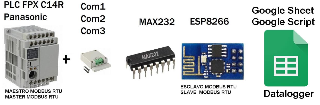
Taking up and improving the applicability of this project integration Scada Web-based SVGESP8266, it has decided to communicate the ESP8266 with a PLC (Programmable Logic Controller) Brand Panasonic FPX C14R, atravez protocol Modbus RTU Serial RS232, Being the PLC Panasonic Master Modbus RTU and Modbus RTUslave ESP8266.
It has an integrated OLED display 128 x 64 communicated via I2C with the ESP8266 for visualization features of the modbus PLC registers.
General objective of the Project
1 ESP8266-01 module with Max232 will connect to the serial port RS232 PLC Panasonic.
2 Integrating Modbus master is routine in the PLC Panasonic with previously programmed strategy in Control FPWIN His Panasonic -Pro software, it is planned to create a monitoring solution Concerning Industrial Controllers values is PLC, PAC, HMI or OPC.
Project Specific Objective
the value of potentiometer V0 PLC Panasonic in a range of 0-1000 escalizado in ESP8266 from 0 to 100% was displayed, the value in a Mini scada webserver based on SVG is visualized, the variation of the potentiometer is noticed almost instantly, for communication between the PLC and ESP8266 is via RS232 Modbus RTU.
By default, the PLC only has 1 Puerto Panasonic 5-pin minidin similar to the PS2 port, the communication port and / or RS232 port programming called Toolport, which can only be configured as:
1 general purpose communication (scales, barcode readers and serial printers)
2 Slave Mewtocol - FP series (Panasonic programming protocol)
Note: No toolport port allows configuration as Master - Slave Modbus RTU
COM4 casette is a expasion communication with 2 ports COM1 (RS485) and COM2 (RS232)
It was used COM2 (RS232).
Additional port settings
Modbus RTU Master Routine
Control Strategy in FPWIN Pro
(* Potenciometer -Potenciometro V0 *)
Pot_PLC:=sys_iPotiInputV0/10; (* Convert value 1000 -> 100 *)

(* Escritura de PLC Como Maestro Modbus RTU *)
(* Write de PLC Como Maestro Modbus RTU *)
IF (sys_bPulse1s AND sys_bIsComPort2F145F146NotActive  ) THEN

F145_WRITE_DATA_TYPE_OFFS(Port := SYS_COM2_PORT,
   SlaveAddress := 1,
   MasterWordData := Pot_PLC,
   SlaveWordAddressType := DT0,
   SlaveWordAddressOffs := 0,
   NumberOfWords_BitsInWords := 16#001);

END_IF;
Has made the connection module for 3.3V TTL serial part to a MAX232 (TTL to RS232 converter) for voltage levels between the communication ports are the same, the module must not exceed feed this voltage 3.3v .
By typing the IP address assigned to the module ESP8266 from any browser will connect directly to this website which will display the following screen shot.
Technically an HTML web server (ESP8266) which seeks an SVG file created, modified and updated in the server root (ESP8266) is created, which makes the entire website is not updated only part that is the SVG this think it is allowing more dynamic to create the SVG directly into the HTML which would require upgrading the entire website.
It has also built an OLED display 128 x 64 connected to ESP8266 via I2C protocol, connected by GPIO 0 and 2, it has been added to make the value display in real time and allows it to be more
complete the test, the displayed value is the value from 0 to 100% relative to the potentiometer PLC.
I present the Panasonic FP-X (Nais -Aromat) series Controllers PLCs or Programmable Logic has evolved, this series the successor to the FP1 series with a small and larger memory size and speed processing value optimized for control systems motion has a varidade of cassettes Ethernet communication protocols RS232 - RS422 and RS485 has the possibility of expansion of inputs and outputs also allows control of the units or expasiones inputs and outputs FP0R his cousin.
Special characteristics
-Speed Scan very fast 0.32μs program
-Protection Program with a password of 8 digits
-Allows Use 3 communication ports simultaneously.
Easy upgrade program is only connect and program.
-Allows The creation and configuration of high precision PID loops
-Total Hardware and software compatibility with any PLC of the Panasonic brand.
Presentation PLC Panasonic
Integrations Panasonic PLC and Arduino
The main idea is to make integration of this PLC (Harware Industrial) ESP8266 with the Arduino platform and using the Protocol itself and Panasonic FP series supported Modbus RTU protocol
This time I have communicated the Arduino with Panasonic PLC and I checked the Arduino useful in the industrial field direfencia of the previous tutorials I've tested both devices communicating via RS - 232.
Summary
1. The arduino send via modbus ADC value 0 to Holding Register 0 and the plc into a strategy compared as follows Arduino
If ADC> 500
relay output PLC = 1
else
PLC relay output = 0
2. The PLC send the value 2 of its potentiometers from 0 to 1000 and displayed on the display arduino Oled, the respective values
PLC FPX C14R Panasonic
Programmable Logic Controller used in industrial in this case the family FPX panasonic (Aromat - Nais)
This PLC has Modbus RTU protocol as master and slave To configure a teacher must create a strategy, if set as slave does not require code as the default plc is a slave and records are automatically routed.
On this occasion I made our arduino communication with HMI Panasonic GT01 monochrome display via RS232 Modbus RTU, Arduino screen as Master and slave.
Summary
1 The value of the ADC 0 of arduino from a potentiometer 100 k will be displayed on the HMI Panasonic
2 The value entered from a keypad from the HMI was displayed from the arduino oled screen.
one Max232 physical is required for communication between the Arduino and the Panasonic screen
GTWIN Panasonic
The Panasonic GT01 screen is programmed into the software GTWIN
records are redirected follows:
GDT0 = Holding Register [0]
GDT1 = Holding Register [1]
1. Communication parameters Screen
2. Modbus RTU Slave
3. Design Screens
Arduino code
Arduino is configured for reading and writing 10 log 10 records.