Testing the ESP8266 03 have noticed differences with ESP version 01.
By default brings AT commands, using the example blink and modifying 02 to activate the GPIO output.
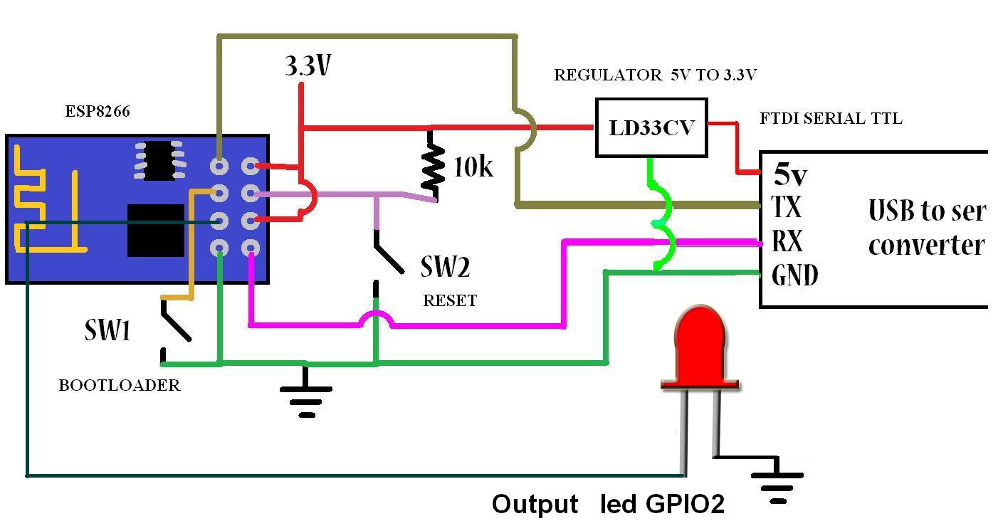
Connection to Program ESP
Should the GPIO 0 to GND to place the bootloader mode module, its programming is equal to ESP 01 only this one does not have RST and should have the GPIO 15 to GND
ESP8266 03
I have done extensive testing withESP8266 01 (ESP 01), I think it has endless applications, but I decided to test another module of the same family, in this case ESP8266 03 (ESP03), say that your great serious advantage has 7 GPIO (I / O).
Characteristics
1. Support 802.11 B/G/N
2. Communication range up to 100 yards depending on environment.
3. Standard 3.3VDC operation with 5V compatible I/O.
4. Standard 3 wire (TXD/RXD/GND) serial communication (idle high) at 115200/8/N/1.
5. Standard 0.1" (2.54mm) half through hole.
6. Upgradeable firmware.
7. Three mode of operations: Client/Access Point/Both Client and Access Point.
8. Support all major security schemes: OPEN/WEP/WPA_PSK/WPA2_PSK/WPA_WPA2_PSK.
9. Support both TCP and UDP communication.
10. Working as TCP/UPD server supports up to five (5) connections.
11. Working as station can connect up to 5 TCP/UPD servers.
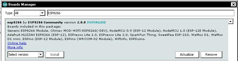
This ESP8266 default module that works by AT commands, thanks to the contributions of the community has made integration with Arduino IDE.
This module (ESP8266) integrates the capabilities of an Arduino + Wifi (Ethenet) and easily the perfect combination for more or less one dollar, just personally I use in my applications in industrial integration, this module is perfect.
Installing ESP8266 in Arduino IDE is only valid from version 1.6.4 and above, in my case there are newer versions but I liked the version 1.6.4 and it worked perfect.
Video step by step explanation Installation and configuration Arduino IDE
This evidence although simulate other tests carried out in previous Post implemented Arduino and protocol Modbus RTU serial master mode, is the first step for connecting arduino an environment Scada Industrial we will see more before implementing Modbus TCP IP, if you want to see continue in PDAControl final application. Other Implementations Arduino and Modbus RTU: Modbus RTU Master Library tests with Arduino Modbus RTU Master tests with Arduino via RS232 and screen Panasonic GT01 Modbus RTU Master tests with Arduino via RS232 and PLC Panasonic FPX C14R Explanation of Application
In this test we will read a potentiometer 100k connected to the input analog 0, the value of ADC0 0-1023 be transmitted via Modbus RTU Simulator Master Modbus in Holding Register [11] and this transmitted value is displayed on the display oled Connected to the Arduino via I2C.
Materials
1- Arduino MEGA 2560 R3
2- Display Oled 128 x 64
3- Poteciometer 100K
Mounting
ADC0 visualization on display Oled
Video of tests
Arduino MEGA 2560 Master Modbus Potenciometer Display Oled I2C
It is a project in development based on open source developed by Trystan Lea, this application has tools for measuring energy or electricity consumption, mixing hardware and software which is available to anyone who wants to start measuring and regulation of energy consumption the purpose of this project is sustainable development.
Arquitecture Openenergy Monitor
You have the ability to create your own hardware and adapt or contribute to the development of software compatible with Arduino and Raspberry Pi,
Implements the measurement and monitoring of variables atravez hardware nodes implementing opensource
It has a management income users with login and password
sending data is encoded with a unique key to avoid collisions Notifies the updating of variables, graphs indivisuales, comparative It has a great tool dashboards equivalent to a scada interface
All our hardware units are fully open-source and based on Arduino. Firmware sketches are available open-source on GitHub. See Resources for info on how to setup Arduino IDE.
Step by Step Installation Emoncms in Windows 7
Install Emoncms on Windows Part 1
Install Emoncms on Windows Part 2
Emoncms more tests on other platforms..............
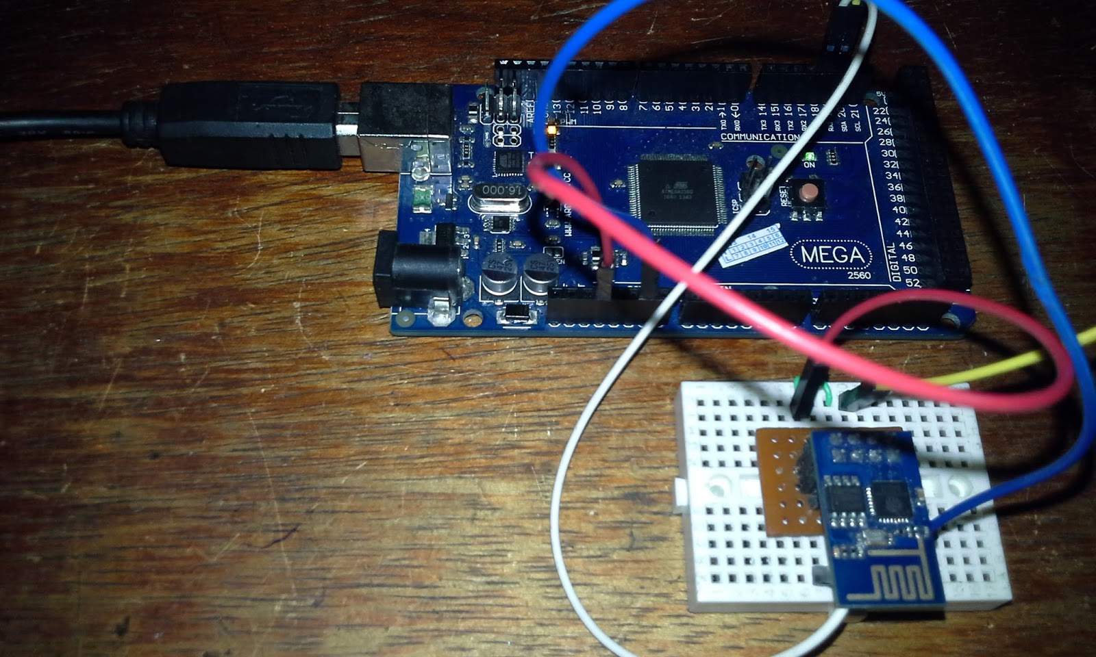
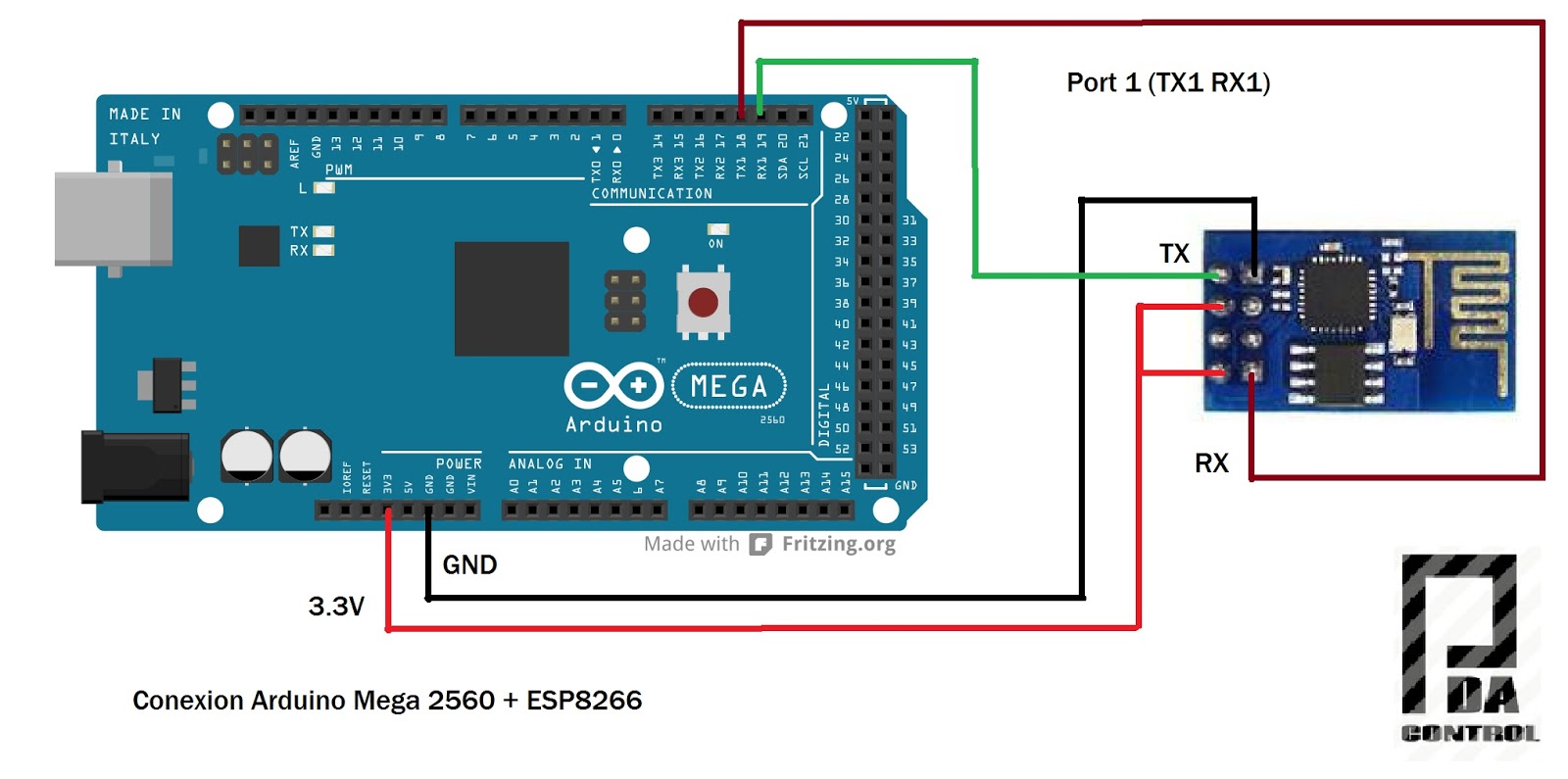
This test is performed given the lack of use of serial ports Arduino Mega 2560 and test communication between the Arduino Mega 2560 and ESP8266 module,
test has been conducted, data take into account, in this case the ESP8266 has been configured to work with AT command Firmware v0.9.5.2 module 115200 baud rate.
Extra Note: If you need Esp8266 Firmware Update.
Test Connections
Materials :
1 Arduino Mega 2560 R3
1 Modulo ESP8266
connections
Test
It has created a strategy bidirectional connection between Port 0 (Serial USB) and Port 1, this test everything that is written in the terminal Arduino be sent to ESP8266 and vice versa, thus the correct communication is depurará ESP8266 module.
Strategy
Test from Terminal
From the Arduino IDE serial terminal it was sent test the following commands:
I have seen many examples of how to control the Arduino remotely but require excessive settings and when using either ethernet LAN or WLAN communication in most examples only works on a local network or intranet.
It tryied a simple way to control using the IRC Chat forgotten and implement it in the ESP8266 module.
The IRC is simple communication since communication is performed between clients, the server is on the network and data values or specific characters sent automatically handles routing.
Explanation of application
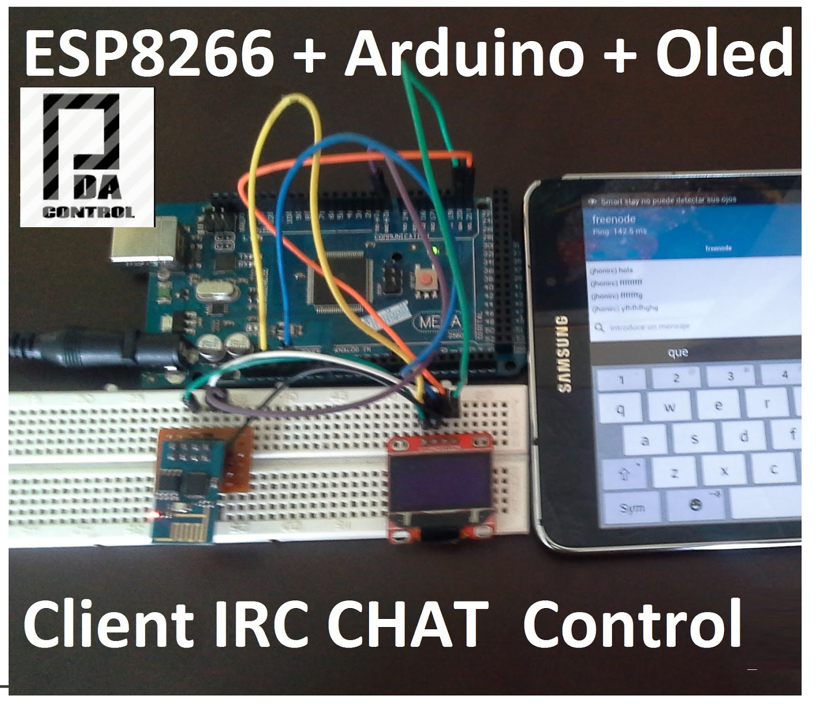
1. In this test the ESP8266 module performs the IRC connection to an IRC server, the room defined using a Nickname.
2. using in this case an IRC client android I connect to the same server and the same room with another nickname and retransmits the module received by the serial port.
3. The Arduino Mega 2560 Just print characters received in the Oled display and performs the activation of inputs and outputs
Materials
Arduino Mega 2560
Display Oled 128 x 64 I2c
ESP8266 - 01
To make this project requires read before the following:
Important note:
In this case it is only control from any client IRC is the only ESP8266 receives, in this test is not yet implemented the ESP8266 send messages, although perform the test and working properly.